Thanks to Natasha for sending me this link. Precious plastic shares the technology to build your own modular plastics recycling workshop.
Category: Technology
Devices
I tend to let my students have a lot of freedom to use their myriad technological devices as they will. Just as long as they use them responsibly (i.e. for academics during class time). What’s most interesting these days is seeing how they combine the various electronics.

This Chemistry student is referring to her textbook on the iPad, while she creates a presentation on her laptop. Yet pen and paper are still integral parts of the process.
3d Printing at School

One of the key ideas behind the design of the RepRap 3D printer we just built is that you should be able to print as many of the components as possible. So you can use your 3D printer to build other 3D printers. As a consequence, the printer does not come as a nice little box. It looks a bit jury-rigged. Multicolored coils of wire snake everywhere; circuit boards and integrated chips are exposed; nuts, bolts and stainless steel rods are accessible for easy adjustment; and the plastic–printed–components are still rough from the printer. It is all function, no aesthetics. All of which make it a wonderful teaching tool.
The three students who built it got a crash course in robotic assembly. They learnt how to wire a power source, strip and solder wires, and construct the motor-controlled bed and extruder. They also learned how to use constructive solid geometry (using OpenSCAD) to create 3d shapes–I required them to design and print their own models before I would let them download object files from the internet.
On the down side, though they did have to plug a RAMPS motor shield, stepper-driver chips, and connecting wires into the Arduino microcontroller, we did not have much time to go into the detail of what it all was about. Also, we only edited an existing configuration file when we tried to calibrate the machine, so they did not learn how the programming works. Having to use the Arduino did inspire me to get one, and I was quite impressed with their starter kit, so I’m working on a “Microcontrollers for Beginners” type class or elective that I can offer over the next school year.
Arduino for Beginners

I’ve been avoiding working with the Arduino microcontrollers because I’d prefer to be able to program in Python with the Raspberry Pi (for example). However, since the 3d printer we just built this summer uses an Arduino for a brain, I broke down and picked up the Arduino Starter Kit (via Adafruit).

What I liked most about the Starter Kit most is the Arduino Projects Book that comes with it. It’s a wonderful introduction to circuits, electronics, circuit diagrams, and microcontrollers at the beginners level. If I offer an Arduino elective, I’ll use it as a textbook. Indeed, I’ll probably use bits of it as a reference when I teach circuits in middle school and Advanced Physics.
As for the programming, the basics, at least, are pretty straightforward. I got a blinking LED controlled by a switch input up an running pretty quickly. The code requires two loops, one to set up the inputs and the output, and a loop for the program to follow. The code below has a blinking light that’s controlled via pin 4, but changes to a solid light when the switch is pressed (the input for the switch is pin 2). The wiring for the circuit is shown in the picture at the top of the page.
blink_circuit
int switchOn = 0;

void setup(){
  pinMode(2, INPUT);
  pinMode(4, OUTPUT);
}

void loop(){
  switchOn = digitalRead(2);

  if (switchOn == HIGH) {
    digitalWrite(4, HIGH);
  } else {
    digitalWrite(4, LOW);
    delay(500);
    digitalWrite(4, HIGH);
    delay(200);
  }

}
Building a Guitar
This week I’m learning how to build an electric guitar–from scratch (or almost). Tom Singer, a professor in design and manufacturing at Sinclair Community College in Dayton, Ohio, is the lead on an NSF funded project to bring guitar building into schools.
I may have a tin ear when it comes to music, but there is quite the interest in guitar playing at the Fulton School at the moment–all the way from the elementary kids to the high schoolers–so I thought it would be a good catch-the-imagination mechanism for use in math and science.
Bodies

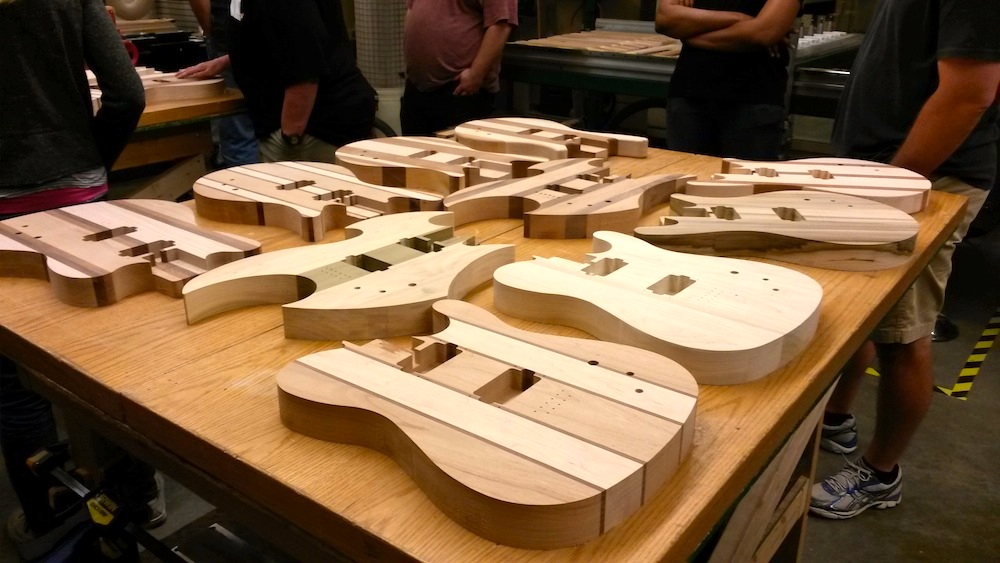
First we got to choose a guitar body. The guitarbuilding team had a fair collection of guitar shapes for the group in the workshop to choose from. The shapes are cut from 1.75 inch thick woo. To get the elegant layered patterns you see above, they laminate about half a dozen different types of wood. This may make for beautiful guitars, but the different densities and hardnesses of the wood have to be considered when working with them. The darker colored woods in the guitar body above were much harder to shave and sand than the lighter colored material.
Note to self: Indeed, if I remember to get hold of some scrap pieces of the different woods, I can probably make up a nice density measuring project. Indeed, it would be nice to have students graph the relationship between density and hardness. Wood hardness is measured on the Janka scale. I suspect there is a positive relationship, but I’d like to see if we could determine the shape of the curve.
Not all of the guitar bodies are beautiful laminates, however. Some, of a single type of wood, are the best candidates for painting. Others are hollowed out, and can be played acoustically as well as plugged in.
Neck and Fretboard
Today I learned what a fretboard is. Apparently it’s a separate piece with the gradational markings that’s attached to the neck.

The necks were all of maple, if I remember correctly, but the fretboards were made of different types of wood. Each was a single piece of wood, but the wood’s hardness and affects the “brightness” of the sound produced by the guitar.
So now it’s time to sculpt and sand the body, and put all the pieces together.
Volumes of Rotation: The Disk Method: 3d with Javascript Three.js
Finally, relatively easy interactive 3d on the web. You can rotate and zoom into the scene. (Although it may not yet be compatible with all browsers it does work with Firefox at least).
This method uses the three.js Javascript library. Here I use it to show the volume of a rotated surface using the disk method. It’s almost identical to my calculus student’s project, except here I’m finding the volume between x=1 and x=3, using disks that are 0.5 units in height (Δx).
Since the volume of cylinder is:

where r is the radius of the cylinder.
We’re finding the volume created by a function that’s rotated around the x-axis. Using the function:

The radius of each cylinder is the value of the function for that x value, so you could write the radius as:

Therefore the volume of each disk is:

There are four disks and we use the function value at the far end of the disk to draw the disk so the total volume is:

Factoring out the π and the Δx gives:

Since Δx = 0.5, a = 1.0, and b = 3.0, we can define the number of disks as n = 4 then we can rewrite using summation formula:

reverting back to a and b gives the general equation:

where:

Light and Sound with a Raspberry Pi
Although it took us a day to figure out how to get the Raspberry Pi to work–a faulty SD card turned out to be a major delay–we still had most of a week of the Creativity Interim for students to get some projects done.
That is, until it started to snow. We lost more two days.
Still, we had a small cadre of determined students, one of whom (N.D.) decided that she wanted to make the Pi play sounds to go with the blinking LED lights.
To do this she needed to:
- Learn how to use the LINIX command line to connect to the Pi and execute programs.
- Learn how to write programs in Python to operate the Pi’s GPIO (input/output) pins.
- Learn how to make circuits on a breadboard connected to the Pi.
A Quick and Incomplete Introduction to the Command Line: Basic Navigation
We started by using the Terminal program on my Mac to learn basic navigation.
To see a list of what’s in a folder use ls:
> ls
For more details on the items in the folder, use the -l option:
> ls -l
To see all the options available for the ls command you can lookup the manual using man:
> man ls
To create a new directory (e.g. Pi) use mkdir:
> mkdir Pi
To change directories (say to go into the Pi directory) use cd:
> cd Pi
Connecting to the Pi
I detail how to connect to a Pi that’s plugged into the wall via the local network here, but to summarize:
Use ifconfig to find the local IP address (under eth1).
> ifconfig
Use nmap to identify where the Pi is on the network. E.g.:
> sudo nmap -sP 191.163.3.0/24
Finally, connect to the Pi using the secure shell program ssh:
> ssh pi@191.163.3.214
(the default password is “raspberry”)
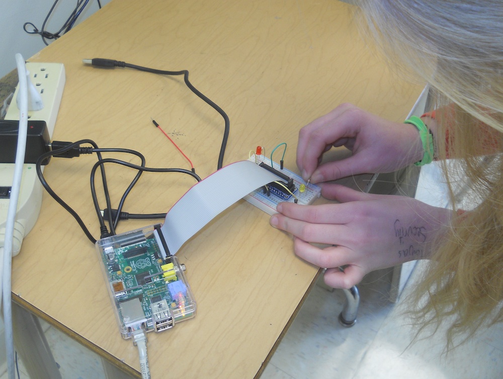
Wiring an LED Light Circuit
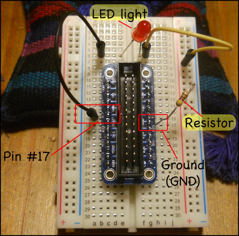
We created an initial circuit going from the #17 General Purpose Input/Output (GPIO) pin to a red LED then through a resistor then back into one of the ground pins of the Pi. We’ll turn the current going through GPIO #17 on and off via our program on the Pi. The resistor is needed to reduce the amount of current flowing through the LED, otherwise it would likely get blown out. The circuit is shown in the picture where I’ve taken the wire ribbon out for the sake of visibility.
Wiring on a breadboard is quite simple if you remember a few rules.
First, the columns of holes on the sides are connected vertically, so the right end of the yellow wire (in the + column) is connected to the resistor.
Secondly, the holes in the middle are connected horizontally, but not across the gap in the middle. That’s why the GPIO pin #17 is connected to the lower end of the black wire, and the left end of the resistor is connected to the ground (GND) pin. The LED light reaches across the two gap to connect the two rows with the upper end of the black wire and the left end of the yellow wire. Without something to bridge the gap, the circuit would not be complete.
The resistor has a resistance of 420 Ohms. You can tell by the color bands. In the sequence–yellow, red, brown–the first two bars represent numbers (yellow=4; red=2) and the third number represents a multiplier (in this case brown represents 10x).
Light: Programming the Pi in Python
Once you ssh to the Pi you can start programming. We used the command line text editor Nano. A simple text editor is all you need to write simple Python programs. We’ll create a program called flash.py (Note: it’s important to include the .py at the end of the file’s name, otherwise it becomes hard to figure out what type of file something is, and the extension also clues Nano in to allow it to color-code the keywords used in Python, making it a lot easier to write code.
pi> nano flash.py
You can then type in your program. The basic code for making a single light flash on and off ten times (see here) is:
flash.py
#!/usr/bin/env python

from time import sleep
import RPi.GPIO as GPIO

cpr = 17  ## The GPIO Pin output number

GPIO.setmode(GPIO.BCM) ## Use board pin numbering

GPIO.setup(cpr, GPIO.OUT) ## Setup GPIO Pin 7 to OUT

for i in range(10):
	GPIO.output(cpr, True)
	sleep(0.5)
	GPIO.output(cpr, False)
	sleep(0.5)
GPIO.cleanup()
This requires wiring a circuit to the GPIO pin #17. The circuit has a LED and a resistor in series, and circles back to the Pi via a grounding pin.
Run the program flash.py using:
pi> sudo python flash.py
Finally, let’s tell the program how many times to flash the light. We could create a variable in the Python code with a number, but it’s more flexible to set Python to take the number from the command line as a command line argument. Any words you put after the python in the command to run your program are automatically stored in an array called sys.argv if you import the sys module into your program. So we rewrite our flash.py program as:
flash2.py
#!/usr/bin/env python

from time import sleep
import RPi.GPIO as GPIO
import sys

cpr = 17  ## The GPIO Pin output number

GPIO.setmode(GPIO.BCM) ## Use board pin numbering

GPIO.setup(cpr, GPIO.OUT) ## Setup GPIO Pin 7 to OUT

for i in range(int(sys.argv[1])):
	GPIO.output(cpr, True)
	sleep(0.5)
	GPIO.output(cpr, False)
	sleep(0.5)
GPIO.cleanup()
So to flash the light 8 times use:
pi> sudo python flash2.py 8
Note that in your Python code you use int(sys.argv[1]) to get the number of times to flash:
- sys.argv[1] refers to the first word on the command line after the name of the python file. sys.argv[0] would give you the name of the python file itself (flash.py in this case).
- the int function converts strings (letters and words) into numbers that Python can understand. When Python reads in the “8” from the command line it treats it like the character “8” rather than the number 8. You need to tell Python that “8” is a number.
Sound: Using SOX
You can do a lot with sound–record, play files, synthesize notes–on the Pi using the command line program SOX. Install SOS (and mplayer and ffmpeg which are necessary as well) using:
pi> sudo apt-get install sox mplayer ffmpeg
Installation may take a while, but when it’s done, if you plug in speakers or headphones–the Pi has no onboard speakers–you can test by synthesizing an E4 note, which has a frequency of 329.63 Hz (via Physics of Music Notes), that lasts for half a second using:
pi> play -n synth .5 sin 329.63
Now play is a command line program that’s part of sox, so to use it in your Python program you have to tell Python to import the module that lets Python talk to the command line: it’s called os. Then you make a Python program to play the note using os.system like so:
test_sound.py
import os
os.system('play -n synth .5 sin 329.63')
And run the program with:
pi> sudo python test_sound.py
Combining light and sound
Now we bring the light and sound together a the Python program:
flash-note.py
#!/usr/bin/env python

from time import sleep
import RPi.GPIO as GPIO
import sys
import os

cpr = 17  ## The GPIO Pin output number

GPIO.setmode(GPIO.BCM) ## Use board pin numbering

GPIO.setup(cpr, GPIO.OUT) ## Setup GPIO Pin 7 to OUT

for i in range(int(sys.argv[1])):
	GPIO.output(cpr, True)
	os.system('play -n synth .5 sin 329.63')
	GPIO.output(cpr, False)
	sleep(0.5)
GPIO.cleanup()
which you run (repeating the note and light 5 times) with:
pi> sudo python flash-note.py 5
Notice that we’ve replaced the middle sleep(0.5) line with the call to play the note because we don’t need the delay since the note plays for 0.5 seconds.
Playing a Tune
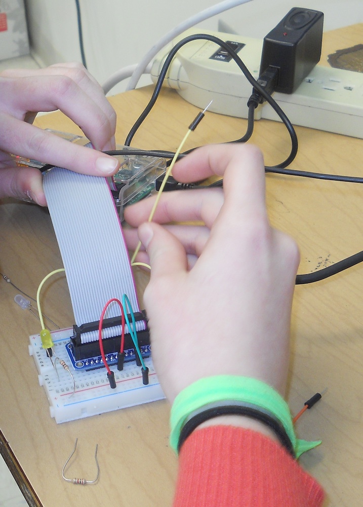
The student, N.D., spent some time working through this programming and adding wiring to the Pi breadboard in order to play the first few notes of Mary Had A Little Lamb. By the time we ran out of time, and she had to do her presentation to the rest of the upper-school, she’d come up with this:
red-light-flash.py
#!/usr/bin/env python

from time import sleep
import os
import sys
import RPi.GPIO as GPIO
os.system('play -n synth 2 sin 543.21')

cpy = 22
cpr = 17
cpw = 23

GPIO.setmode(GPIO.BCM) ## Use board pin numbering

GPIO.setup(cpy, GPIO.OUT) ## Setup GPIO Pin 0 to OUT
GPIO.setup(cpr, GPIO.OUT)
GPIO.setup(cpw, GPIO.OUT)

for i in range(int(sys.argv[1])):
	GPIO.output(cpy, True)
	GPIO.output(cpr, False)
	GPIO.output(cpw, False)
	os.system('play -n synth 1 sin 578.00')
	GPIO.output(cpy, False)
	GPIO.output(cpr, True)
	GPIO.output(cpw, False)
	os.system('play -n synth 2 sin 440.00')
	GPIO.output(cpy, False)
	GPIO.output(cpr, False)
	GPIO.output(cpw, True)
	os.system('play -n synth 1 sin 400.00')
GPIO.cleanup()
which is run (5 times) using:
pi> sudo python red-light-flash.py 5
Creating User-Defined Functions
(As a note to N.D., because we ran out of time before we could get to it.)
You’ll notice it takes four lines to turn a light on, turn the other lights off, and play the note. You’ll also note that you have to repeat the exact same code every time you want to play a specific note and it becomes a pain having to repeat all this every time, especially if you want to play something with more notes. This is the ideal time to define a function to do all the repetitive stuff.
So we’ll create a separate function for each note. Mary has a little lamb uses the notes E4, D4, and C4. So we get their frequencies from Physics of Music Notes and create the functions:
def e4():
	GPIO.output(cpy, True)
	GPIO.output(cpr, False)
	GPIO.output(cpw, False)
	os.system('play -n synth .5 sin 329.63')

def d4():
        GPIO.output(cpy, False)
        GPIO.output(cpr, True)
        GPIO.output(cpw, False)
        os.system('play -n synth .5 sin 293.66')

def c4():
        GPIO.output(cpy, False)
        GPIO.output(cpr, False)
        GPIO.output(cpw, True)
        os.system('play -n synth .5 sin 261.63')
now we can plug these functions into our code and call the notes pretty easily just by using the names of the functions:
flash-mary.py
#!/usr/bin/env python

from time import sleep
import os
import sys
import RPi.GPIO as GPIO

def e4():
	GPIO.output(cpy, True)
	GPIO.output(cpr, False)
	GPIO.output(cpw, False)
	os.system('play -n synth .5 sin 329.63')

def d4():
        GPIO.output(cpy, False)
        GPIO.output(cpr, True)
        GPIO.output(cpw, False)
        os.system('play -n synth .5 sin 293.66')

def c4():
        GPIO.output(cpy, False)
        GPIO.output(cpr, False)
        GPIO.output(cpw, True)
        os.system('play -n synth .5 sin 261.63')

cpy = 22
cpr = 17
cpw = 23

GPIO.setmode(GPIO.BCM)


GPIO.setup(cpy, GPIO.OUT)
GPIO.setup(cpr, GPIO.OUT)
GPIO.setup(cpw, GPIO.OUT)

GPIO.setup(sp, GPIO.IN)

for i in range(int(sys.argv[1])):
	print "switch on"
	e4()
	d4()
	c4()
	d4()
	e4()
	e4()
	e4()

GPIO.cleanup()
which can be run (playing twice) with:
pi> sudo python flash-mary.py 2
Getting Started with a Raspberry Pi
Raspberry Pi‘s are small computers that are remarkably easy to use if you know what you’re doing. Unfortunately, I did not quite know what I was doing. On the other hand, fortunately, I had Mr. Schmidt available to give me the kick start I needed to get going. In this post, I’ll outline, in as much detail as possible, how we got started; how we helped a student put together a synchronized LED light and digital sound project.
You should just be able to plug your Pi into a monitor using the HDMI cable that comes with the starter kit (like this kit by Adafruit) and power it up. However, we did not have a monitor that could take an HDMI cable, so we had to connect the hard way: by plugging the Pi into an ethernet cable and finding it on the local network. This is what’s called a headless setup — with no monitor and no keyboard — and I followed a lot of Robert A. Wood’s instructions on headless setups.
Install the Raspbian Operating System for remote access
First you have to make sure you have a bootable operating system on the Pi’s SD card that will allow you to connect remotely through the internet. The card that came with the starter kit had the basic NOOBS operating system installed, but NOOBS does not allow remote access by default.
I downloaded the Raspbian raw image to my computer then copied the image to the SD card using the terminal program dd. Follow this procedure with caution because you can do a lot of damage if you copy the image over your computer’s hard drive (which is remarkably easy to do with dd). The procedure follows:
1) Once you plug the SD card into your computer it should mount automatically. You need to detect where it is mounted using (on a Mac running OSX) the diskutil program:
> diskutil list
This should give you a list of all of your mounted disks. Identify the one that is the SD card. It should look something like this:

It shows my 4 gigabyte disk located at ‘/dev/disk1’.
2) If you’re absolutely sure you’ve identified the SD card you need to unmount it:
> diskutil unmountDisk /dev/disk1
3) Now if you’re still absolutely sure you have the right location of the SD card copy the image. Note that in the example below the option ‘if‘ means input file, while ‘of‘ means output file:
> dd if=~/raspberry/raspi/2014-01-07-wheezy-raspbian.img of=/dev/disk1
I had the devil of a time trying to install the raw image of the Raspbian operating system. After a few hours of frustration I finally pulled an SD card from my small camera and lo-and-behold the copy went through easily. So make sure you have a good quality card.
Talking to the Pi
Plug the SD card with Raspbian installed into the Pi, plug the Pi into a power outlet, then and plug an ethernet cable into the Pi. The Pi should boot up and connect to the internet automatically. Now you just have to find it from your computer. Mr. Schmidt helped a lot with this step, but I also used Pete Taylor’s instructions as well.
The ifconfig command will tell you your computer’s IP address. Look under the section en1.
> ifconfig
My IP address turned out to be 191.163.3.218.
To find the Pi I had to download and install nmap to locate all things on the local network. Once installed I used:
> sudo nmap -sP 191.163.3.0/24
You should find something labeled ‘Raspberry Pi’ with an IP address that’s almost identical to yours except for the last of the four numbers. I found mine at 191.163.3.214.
Now, you can log in to the Raspberry Pi using the username ‘pi’ and the password ‘raspberry’:
> ssh pi@191.163.3.214
And, ‘Bam’, you’re in.
Configure and Update
I used the configuration utility ‘raspi-config’ to expand the root file system to take up the entire SD Card: expand_rootfs:
pi> raspi-config
Update the software using the two commands:
pi> sudo apt-get update
pi> sudo apt-get upgrade
You can also set up the Pi for remote window access by running a Virtual Network Computing (VNC) server and using a vnc client (like Chicken on the Mac). I installed ‘tightvnc’ and started the vnc server on the Pi with:
pi> sudo apt-get install tightvncserver
pi> vncserver :1
We never did end up using the vnc window, however.
The light circuit
We hooked up the LED circuit to the output pin GPIO 17 in series with a resistor and then back into a ground pin of the Pi, pretty much as the Gordon’s Projects page describes.
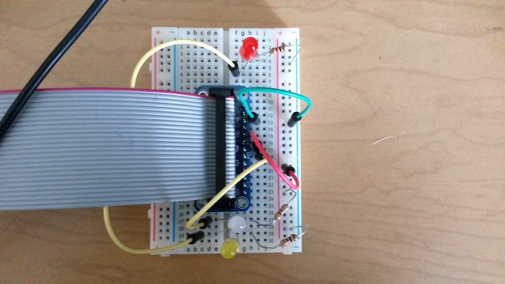
Talking to the Circuits/Pins
In order to get the Pi to operate the LED lights you have to control the pins that communicate in and out. Our starter kit came with a ribbon cable and breakout board that connects the pins from the Pi to a breadboard, which makes it easier to build circuits.
But first we have to be able to control to the Pi’s pins. I tried two different methods. The first was to use wiringPi, which is a set of command line tools, while the second was to use the Rpi.GPIO library for the Python programming language. We found it was much easier to use Python for its ease of programming.
Command line: wiringPi:
To get wiringPi, download it with ‘git‘, go to its directory, then build it (Gordon’s Projects has the instructions):
pi> git clone git://git.drogon.net/wiringPi
pi> cd wiringPi
pi> ./build
Now you can manipulate pin 0 (GPIO 17, which is labeled #17 on the breakout board) by: 1) setting to output mode; 2) turning it on, and; 3) turning it off:
pi> gpio mode 0 out
pi> gpio write 0 1
pi> gpio write 0 0
The following short script (red-light-flash.s) turns the light on and off ten times:
red-light-flash.s
#!/bin/bash
# a single blinking led light attached to gpio0
# based on
# https://projects.drogon.net/raspberry-pi/gpio-examples/tux-crossing/gpio-examples-1-a-single-led/

for i in `seq 1 10`
do
gpio write 0 1
sleep 0.5
gpio write 0 0
sleep 0.5
done
The script needs to be given execute permissions:
pi> chmod 777 red-light-flash.s
then run:
pi> ./red-light-flash.s
Python: Rpi.GPIO
As I mentioned above, it’s much easier to write programs in Python than to use shell scripts. So we’ll install the Python library, RPi.GPIO, to that allows us to communicate with the Pi. To get RPi.GPIO we first need the Python Development toolkit:
pi> sudo apt-get install python-dev
Then install Rpi.GPIO:
pi> sudo apt-get install python-rpi.gpio
To operate the GPIO-17 (turn it on and off every half second) we use the following program:
flash.py
#!/usr/bin/env python

from time import sleep
import RPi.GPIO as GPIO

cpr = 17  ## The GPIO Pin output number

GPIO.setmode(GPIO.BCM) ## Use board pin numbering

GPIO.setup(cpr, GPIO.OUT) ## Setup GPIO Pin 7 to OUT

for i in range(10):
	GPIO.output(cpr, True)
	sleep(0.5)
	GPIO.output(cpr, False)
	sleep(0.5)
GPIO.cleanup()
We run the program using the command:
pi> sudo python flash.py
Addendum: A Student’s Light and Sound Project
During our Creativity interim, one student chose to use the python program flash.py as a starting point to make a program to combine light and musical notes.