PlottyBot: Pen Drawn Plots

The PlottyBot project looks like a nice introductory project for building computer controlled devices, like 3d printers, laser cutters, and CNC machines. It draws designs using a pen, and is built off a Raspberry Pi Zero, which I’ve been using a lot.

A PlottyBot in action (from https://ben.akrin.com/?p=10244)

It’s now on my list of potential Makerspace Projects.

Introduction to Pi’s (Raspberry Pi)

The family of Raspberry Pi’s are just really small computers. You can plug a monitor, keyboard, and mouse into one and it will not look too different from your desktop. They are small and cheap, but what makes them really useful is that they have little slots (called GPIO’s) that you can stick wires into that allow you to build circuits that can get information from sensors and control devices like LED lights or motors.

This is a quick introduction about how to set one up. You’ll find lots of great tutorials on the internet. This one is specific to my needs: it’s an introduction to the Pi’s for students who are new to them; I’m setting it up with a web server so we can control the devices through a webpage; and I’m setting it up so you can control the Pi “headlessly”, which means you don’t need the keyboard, mouse, etc..

Installing the Operating System

Downloading the OS

Download: The operating system files can be downloaded from the Raspberry Pi website. We’re going to use the Raspbian Desktop version with the recommended software.

Your typical computer has a built in hard drive that stores the data you save, the programs/apps you install, and the operating system (OS) that runs it all. When you start the computer the first thing it does is read the files that make up the operating system from the hard drive and set them up in the active, processing memory (RAM). Then when you interact with the computer (type on the keyboard, click the mouse etc.) you’re interacting with the operating system: you tell the operating system what to do, like start up a web browser (Firefox, Chrome, Safari, Explorer, Opera etc.), and it does it. And when your apps want to do something, like save a file, they have to ask the operating system to do it.

On the Raspberry Pi the data for the operating system is not stored on a built in hard drive, but on an SD card (or microSD), which means that you’re going to have to install the operating system yourself to get your Pi running. You can find the operating system at the Raspberry Pi website’s download page.

Installing

As of this writing, I’ve been using balenaEtcher to install the operating system on the SD Card.

balenaEtcher is free and pretty easy to use. Hopefully, your computer has an SD card port, if not you’re going to have to find an adapter. Just plug your SD card into your computer and run Etcher, it will ask you to:

  • Select Image: Which is the Raspbian file you downloaded
  • Select Drive: Which should default to the SD card you plugged in (check the size of the drive to make sure)
  • Flash: Which writes the Operating System files to the SD card, making sure everything is in the right place.

You may see some warnings pop up about Unrecognized Files Systems or similar. You can just close those windows.

When the flashing is done, don’t take the SD card out of your computer (or put it back in if you have) just quite yet. We’re going to set it up so the Pi can automatically connect to the WiFi, which will make it easier to talk to.

Setting Up WiFi

You’re going to have to edit some files on the SD card to give the Pi the information about the WiFi situation so that it can automatically connect. This is most useful if you’re not going to plug in a keyboard and monitor and just want to control the Pi from your computer (more on how to do this later). If you do want to go the keyboard and mouse route, you can just plug the SD card into the Pi, power it up, and set up the WiFi like you would normally do on your laptop.

To edit the files I use Atom on Windows or TextEdit which is built in on Mac. These programs should allow you to easily save files as plain text, without any of the fancy styling that will create errors when the Pi operating system tries to get the information from the files.

WiFi

Create a new file called: “wpa_supplicant.conf” (based on these notes) containing:

ctrl_interface=/var/run/wpa_supplicant GROUP=netdev
update_config=1

network={
 ssid="networkID"
 psk="password"
}

But you have to change:

  • networkID to the name of the WiFi network you’re trying to connect to
  • password to the password for the network

If you need to connect to multiple networks (home and school for example) you can add another network command on a new line after the first one:


network={
 ssid="otherNetwork"
 psk="otherPassword"
}

Save this file to the boot directory of the SD card.

ssh

ssh allows you to remotely connect to your Pi’s operating system. This means that you can use your laptop to control the Pi (however you’ll be using command line commands).

Create an empty file named “ssh” and save it to the boot directory of your SD card.

USB connection

You should be able to find your Pi on the network (I use an app on my phone called Fing) and ssh in. However, to do most of the setup, especially if the Pi has trouble connecting to the WiFi (or you can’t find it on the network), you’ll probably want to set up your pi so you can plug it into your computer’s USB port and control it from the computer. Based on the notes from Adafruit, do this:

Open the file “config.txt” which is in the SD card’s boot directory, and add this as the last line in the file:

dtoverlay=dwc2

Save the file then:

Open the file “cmdline.txt”, find the word “rootwait” and, after it, insert the phrase:

 modules-load=dwc2,g_ether

You should end up with something that looks like “…=yes rootwait modules-load=dwc2,g_ether quiet…”:

Connecting to your Pi

To talk to your Pi’s Operating System you should be able to connect your Pi’s USB port to your computer’s or connect over WiFi. Either way you’ll need to use an ‘ssh’ program.

  • Windows: I use putty. Install the program and run it. Then you’ll need to enter:
    • Host Name: raspberrypi.local
    • Password: raspberry
  • Mac: I use the built-in Terminal (In your Applications->Utilities folder). Type in the command (don’t type in the “>”):
    • > ssh raspberrypi.local
    • Use the password: raspberry

If you go the WiFi route, you’ll need to find your Pi’s IP address and use that as the Host Name.

Update and Upgrade

Once you’re ssh’d in, and are connected the internet, you can update and upgrade the operating system. Type in the commands (without the “>”).

> sudo apt-get update
> sudo apt-get upgrade

The “sudo” means you’re giving yourself permission to run commands that could potentially mess up your system. The program you’re running is called “apt-get” which connects to the internet repositories with the latest updates and upgrades to your operating system and programs, and then downloads and installs them. The options “update” and “upgrade” specifically tells the “apt-get” program what you want it to do. Downloading and upgrading may take a while.

Enable Interfaces

You’ll also want to check that the interfaces to the GPIO pins are enabled, so you can build circuits and control them. Notes on this are here.

First check that your tools are installed and updated with the commands:

> sudo pip3 install --upgrade setuptools
> sudo apt-get install -y python-smbus
> sudo apt-get install -y i2c-tools

Then Activate the Interfaces. You’ll run the command “raspi-config” and then use your keyboard to tab through the windows to activate the I2C and SPI interfaces. These are just two different ways for the Pi to talk to the devices you plug into it.

> sudo raspi-config
---- Interfacing Options
-------- I2C
------------ Yes
---- Interfacing Options
-------- SPI
------------ Yes

To get this all up an running you need to reboot the Pi:

> sudo reboot now

For the OLED displays

To control the little OLED displays we have, install the adafruit-blinka, and OLED libraries:

> sudo pip3 install adafruit-blinka
> sudo pip3 install adafruit-circuitpython-ssd1306

Tornado Server

The tornado server allows us to create webpages on the Pi that we can connect to over WiFi that can be used to control devices connected to the Pi. Install tornado using:

> sudo pip3 install tornado

Now restart everything and we can get to work.

> sudo reboot now

Headless Pi Zero

Pi Zero‘s are even cheaper versions of the Raspberry Pi. The price you pay is that they’re harder to connect to since all the ports are small (micro-USB’s and mini-HDMI’s), so you need adapters to connect to keyboards, mice, and monitors. However, if you have the wireless version (Pi Zero W) you can set it up to automatically connect to the WiFi network, and work on it through there using the command line. This is a brief summary of how to do this (it’s called a “headless” setup) based on Taron Foxworth’s instructions. It should work for the full Raspberry Pi as well.

Set up the Operating System

You can install the Raspbian Stretch (or Raspbian Lite which does not include the desktop GUI that you will not use) on a SD card (I used 8 or 16 Gb cards).

  • Download Raspbian.
  • SD Card Formatter to format the SD Card. It’s pretty quick, just follow the instructions.
  • Etcher: to install the operating system on the SD Card

Set up automatic connection to WiFi

You may have to remove and reinsert the SD Card to get it to show up on the file system, but once you have you can set it up to automatically connect to WiFi by:

  • Go into the /boot partition (it usually shows up as the base of the SD Card on your file manager) and create a file named “ssh”.
  • Create a text file called “wpa_supplicant.conf” in the /boot folder, and put the following into it, assuming that the wifi router you’re connecting to is called “myWifi” and the password is “myPassword”.
  • country=US
    ctrl_interface=DIR=/var/run/wpa_supplicant GROUP=netdev
    update_config=1
    
    network={
     ssid="myWifi"
     scan_ssid=1
     psk="myPassword"
     key_mgmt=WPA-PSK
    }
    

Now put the SD Card into the Pi and plug in the power.

Find the IP address

First you have to find the Pi on the local network. On Windows I use Cygwin to get something that looks and acts a bit like a unix terminal (on Mac you can use Terminal, or any shell window on Linux).

To find the ip address of your local network use:

on Windows:

> ipconfig

look for the “IPv4 Address”.

Mac (and Linux?)

> ifconfig

look under “en1:”

Connecting

To connect you use ssh on the command line (Mac or Linux) or something like Putty

Static IP

Without a static IP address it is possible that the Pi’s IP address will change occasionally. I followed the instructions on Circuit Basics and MODMYPI, but basically you have to:

  • Identify your network information:
    • Find your Gateway:
    • > route -ne
      
    • Find your Domain Server:
    • > cat /etc/resolv.conf
      
  • Add the information to the end of your /etc/dhcpcd.conf file (here the wlan0 means you’re doing this to the wireless interface (WiFi) and the static ip is 10.0.0.99, the static router the gateway ip you found above, and the domain_name_servers takes the domain server ip):
  • interface wlan0
    static ip_address=10.0.0.99
    static routers=10.0.0.1
    static domain_name_servers=75.75.75.75
    
  • Now reboot and you should be able to ssh or sftp into the new static IP.

A Web Server

Adding a webserver (apache with php) is pretty easy as well, just run the commands (from the Raspberry Pi Foundation)

Apache web server:

sudo apt-get install apache2 -y

PHP for server-side scripting

sudo apt-get install php libapache2-mod-php -y

Now your can find the webpage by going to the ip address (e.g. http://10.0.0.1).

The actual file that you’re seeing is located on the Pi at:

/var/www/html/index.html

You will probably need to change the ownership of the file in order to edit it by running:

> sudo chown pi: index.html

Talk Timer

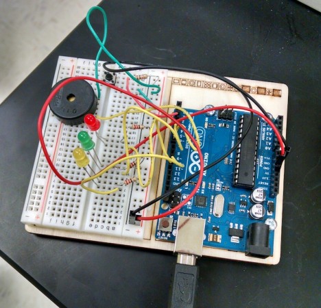
Arduino timer.
Arduino timer.

Given the idea that “learning situated in meaningful contexts is often deeper and richer than learning in abstract contexts,” (Lillard, 2007), I’ve been trying to orient our robotics program toward developing devices that we can use at school. Not only can these devices serve a useful purpose, but their presence around the school can, perhaps, inspire other students to want to make their own.

To this end, one of our first practical projects is a timer (by Joe A.) for when students give their presentations in Chemistry class. For the last round of presentations they had 20 minutes, so I had Joe build the circuits and program the Arduino to make the green light to be on for 15 min, the yellow on for 4 min, the red for 1 min, and then the piezoelectric buzzer would go off for 5 seconds and the red light would start blinking.

Joe did an awesome job, and the timer worked remarkably well. I did what we wanted it to do, and it actually worked to help them keep their presentations under time.

Human Jobs in the Robotic Future

After all the time I spent working with Raspberry Pi microcomputers and Arduino microcontrollers this summer, it was interesting to see Claire Cain Miller summary of a PEW report on “AI, Robotics, and the Future of Jobs“.

Miller provides some interesting quotes from the experts surveyed for the report. One quote stood out in terms of its perspective on education and pedagogy:

“Only the best-educated humans will compete with machines. And education systems in the U.S. and much of the rest of the world are still sitting students in rows and columns, teaching them to keep quiet and memorize what is told to them, preparing them for life in a 20th century factory.”

— Howard Rheingold, tech writer and analyst .

The Key Findings from the PEW report provides a good summary of their results:

Half of these experts (48%) envision a future in which robots and digital agents have displaced significant numbers of both blue- and white-collar workers—with many expressing concern that this will lead to vast increases in income inequality, masses of people who are effectively unemployable, and breakdowns in the social order.

The other half of the experts who responded to this survey (52%) expect that technology will not displace more jobs than it creates by 2025. To be sure, this group anticipates that many jobs currently performed by humans will be substantially taken over by robots or digital agents by 2025. But they have faith that human ingenuity will create new jobs, industries, and ways to make a living, just as it has been doing since the dawn of the Industrial Revolution.

These two groups also share certain hopes and concerns about the impact of technology on employment. For instance, many are concerned that our existing social structures—and especially our educational institutions—are not adequately preparing people for the skills that will be needed in the job market of the future. Conversely, others have hope that the coming changes will be an opportunity to reassess our society’s relationship to employment itself—by returning to a focus on small-scale or artisanal modes of production, or by giving people more time to spend on leisure, self-improvement, or time with loved ones.

— Smith and Anderson, 2014. AI, Robotics, and the Future of Jobs.

The full report is worth a read.

Datalogging with the Arduino

30 seconds of temperature data recorded using the Arduino (over the serial port).

I wired a temperature sensor to my Arduino as part of the third project in the Arduino Projects Book. The project has the Arduino send the data to the serial port where the Arduino program (IDE) can show it. This data would be most useful to me, however, if it could be logged in a plain text file for data analysis. However, it’s a little annoying that there isn’t an easy way to save the data output by the Arduino.

So, I needed to use the terminal program “cat” to look at what was coming across the serial port. First I had to look up which port the Arduino was connected to in the Tools menu of the Arduino IDE: since I’m on a Mac, running OSX, this turned out to be something like /dev/cu.usbmodem411. (I could have looked this up by listing the contents of the /dev/ directory and then looking for anything connected to the usbmodem). To see the data I used:

> cat /dev/cu.usbmodem411 

To actually save the data I directed the output of the cat command to the file data-log.txt:

> cat /dev/cu.usbmodem411 > data-log.txt

The contents of the file looked like this:

T25.68
6003,25.68
7504,25.68
Time (milliseconds), Temperature (deg. C) 
0,25.20
1501,25.68
3002,25.68
4502,25.68
6003,26.66
7504,28.12
9006,30.08
10335,32.03
11663,33.98
12992,35.45
14321,36.91
15650,38.38
16979,39.84
18309,41.31
19559,42.77
20810,43.75
22062,42.77
23313,41.31
24563,40.82
25815,39.36
27144,38.87
28473,37.89
29802,37.40
31131,36.91
32459,35.94
33788,35.45
35118,35.45
36447,34.96
37776,34.47
39105,33.98
40434,33.98
41763,33.50
43091,33.01
44421,33.01
45750,33.01
47079,32.52
48408,32.52
49737,32.52
51066,32.03
52396,31.54
53724,31.54

I’m not sure what’s the deal with the first three lines, but if you ignore them you see the column headers (Time and Temperature) and then the time (in milliseconds) and temperature data) in a nice comma delimited format.

The Arduino program (sketch) that produced this output was:

const int T_sensor_Pin = A0;
const float baselineTemp = 20.0;
const int outPin = 4;

void setup(){
  
  Serial.begin(9600);
  pinMode(outPin, OUTPUT);
  
  Serial.println("Time (milliseconds), Temperature (deg. C) ");

}

void loop(){
  int T_sensor_Val = analogRead(T_sensor_Pin);
  
  float T_sensor_Voltage = (T_sensor_Val * 5.0)/1024.0;
  
  float T = (T_sensor_Voltage - 0.5) * 100;
  float T_F = (T * 1.8) +32.0;
  
  Serial.print(millis());
  Serial.print(",");
  Serial.println(T); 

  delay(1500);
  
}

Alternative Methods of Saving Data

Python

Based on the same Arduino sketch, you can write a Python program to read the data. This method enables you to use the data directly with VPython for visualization.

First you need to install the pySerial library (pySerial). Then you can read the serial data using:

data-log.py

import serial

ser = serial.Serial('/dev/cu.usbmodem411', 9600)

while True:
    print ser.readline()

CoolTerm

You can also use CoolTerm to save the serial data (see directions on how).

An SD Card

Another alternative, is to get a shield that can hold an SD card (SparkFun and Adafruit have ones for less than $20) and write to that.

3d Printing at School

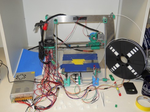
The  RepRap 3D printer.
The RepRap 3D printer.

One of the key ideas behind the design of the RepRap 3D printer we just built is that you should be able to print as many of the components as possible. So you can use your 3D printer to build other 3D printers. As a consequence, the printer does not come as a nice little box. It looks a bit jury-rigged. Multicolored coils of wire snake everywhere; circuit boards and integrated chips are exposed; nuts, bolts and stainless steel rods are accessible for easy adjustment; and the plastic–printed–components are still rough from the printer. It is all function, no aesthetics. All of which make it a wonderful teaching tool.

The three students who built it got a crash course in robotic assembly. They learnt how to wire a power source, strip and solder wires, and construct the motor-controlled bed and extruder. They also learned how to use constructive solid geometry (using OpenSCAD) to create 3d shapes–I required them to design and print their own models before I would let them download object files from the internet.

On the down side, though they did have to plug a RAMPS motor shield, stepper-driver chips, and connecting wires into the Arduino microcontroller, we did not have much time to go into the detail of what it all was about. Also, we only edited an existing configuration file when we tried to calibrate the machine, so they did not learn how the programming works. Having to use the Arduino did inspire me to get one, and I was quite impressed with their starter kit, so I’m working on a “Microcontrollers for Beginners” type class or elective that I can offer over the next school year.

Arduino for Beginners

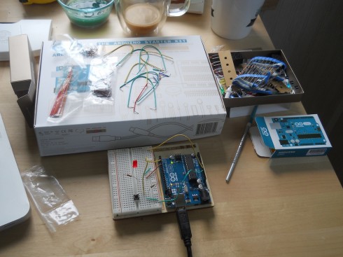
Arduino UNO connected to a breadboard from the starter kit.

I’ve been avoiding working with the Arduino microcontrollers because I’d prefer to be able to program in Python with the Raspberry Pi (for example). However, since the 3d printer we just built this summer uses an Arduino for a brain, I broke down and picked up the Arduino Starter Kit (via Adafruit).

The Arduino Projects Book is an excellent resource for the beginner.

What I liked most about the Starter Kit most is the Arduino Projects Book that comes with it. It’s a wonderful introduction to circuits, electronics, circuit diagrams, and microcontrollers at the beginners level. If I offer an Arduino elective, I’ll use it as a textbook. Indeed, I’ll probably use bits of it as a reference when I teach circuits in middle school and Advanced Physics.

As for the programming, the basics, at least, are pretty straightforward. I got a blinking LED controlled by a switch input up an running pretty quickly. The code requires two loops, one to set up the inputs and the output, and a loop for the program to follow. The code below has a blinking light that’s controlled via pin 4, but changes to a solid light when the switch is pressed (the input for the switch is pin 2). The wiring for the circuit is shown in the picture at the top of the page.

blink_circuit

int switchOn = 0;

void setup(){
  pinMode(2, INPUT);
  pinMode(4, OUTPUT);
}

void loop(){
  switchOn = digitalRead(2);
  
  if (switchOn == HIGH) {
    digitalWrite(4, HIGH);
  } else {
    digitalWrite(4, LOW);
    delay(500);
    digitalWrite(4, HIGH);
    delay(200); 
  }
  
}