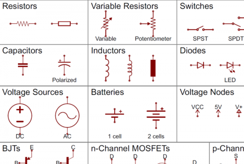
Sparkfun , which is an excellent purveyor of microelectronics (including Raspberry Pis and Arduinos), has a very nice tutorial that useful forhttps://learn.sparkfun.com/tutorials/how-to-read-a-schematic.
Middle and High School … from a Montessori Point of View

Sparkfun , which is an excellent purveyor of microelectronics (including Raspberry Pis and Arduinos), has a very nice tutorial that useful forhttps://learn.sparkfun.com/tutorials/how-to-read-a-schematic.
Ben Eater’s excellent series on building a computer from some basic components. It goes how things work from the transistors to latches and flip-flops to the architecture of the main circuits (clock, registers etc). The full playlist.
Other good resources include:
Studying voltage and current in circuits can start with two laws of conservation.
Note: Some of the links are dead, but this MIT Opencourse pdf has a detailed explanation. And Kahn Academy has some videos on the current laws as well.


Things get more interesting when we get away from simple circuits.
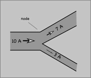
Note that the convention for drawing diagrams is that the current move from positive (+) to negative (-) terminals in a battery. This is opposite the actual flow of electrons in a typical wired circuit because the current is a measure of the movement of negatively charged electrons, but is used for historical reasons.
Based on the MIT OpenCourseWare Introduction to Electrical Engineering and Computer Science I Circuits 6.01SC Introduction to Electrical Engineering and Computer Science Spring 2011.
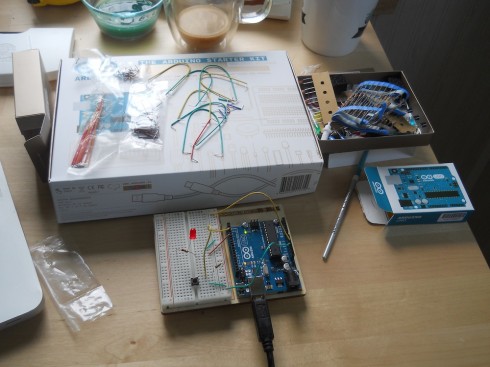
I’ve been avoiding working with the Arduino microcontrollers because I’d prefer to be able to program in Python with the Raspberry Pi (for example). However, since the 3d printer we just built this summer uses an Arduino for a brain, I broke down and picked up the Arduino Starter Kit (via Adafruit).
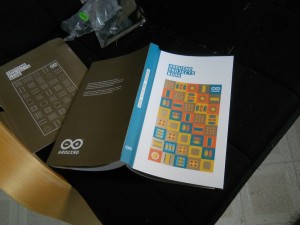
What I liked most about the Starter Kit most is the Arduino Projects Book that comes with it. It’s a wonderful introduction to circuits, electronics, circuit diagrams, and microcontrollers at the beginners level. If I offer an Arduino elective, I’ll use it as a textbook. Indeed, I’ll probably use bits of it as a reference when I teach circuits in middle school and Advanced Physics.
As for the programming, the basics, at least, are pretty straightforward. I got a blinking LED controlled by a switch input up an running pretty quickly. The code requires two loops, one to set up the inputs and the output, and a loop for the program to follow. The code below has a blinking light that’s controlled via pin 4, but changes to a solid light when the switch is pressed (the input for the switch is pin 2). The wiring for the circuit is shown in the picture at the top of the page.
blink_circuit
int switchOn = 0;

void setup(){
  pinMode(2, INPUT);
  pinMode(4, OUTPUT);
}

void loop(){
  switchOn = digitalRead(2);

  if (switchOn == HIGH) {
    digitalWrite(4, HIGH);
  } else {
    digitalWrite(4, LOW);
    delay(500);
    digitalWrite(4, HIGH);
    delay(200);
  }

}
The greater the resistance (R) of a circuit, the less current (I) will flow through it (an inverse relationship). The equation is:
Current = Voltage / Resistance

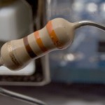
Resistors can be actual resistors, lamps, toasters, or anything else that uses electricity. Even the wires have resistance (but we don’t usually consider that since it’s small compared to the resistance of the other stuff).
The total resistance of a circuit depends on the way the resistors are arranged:
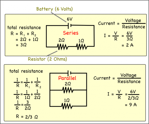
(Notes: Current is a bit like water flowing through a pipe. Resistors are blockages that slow down the flow. Put two blockages, one after the other, and you reduce the flow rate. If you put two blockages into two different channels then though each one slows down flow the total flow is larger.)
As you put in more and more parallel circuits you draw more and more current until you overload the circuit and the wires heat up enough to burn through their insulation. Fuses (or circuit breakers) are used to prevent this; they burn out, breaking the circuit, when too much current goes through them.
Questions: