Raspberry Pi‘s are small computers that are remarkably easy to use if you know what you’re doing. Unfortunately, I did not quite know what I was doing. On the other hand, fortunately, I had Mr. Schmidt available to give me the kick start I needed to get going. In this post, I’ll outline, in as much detail as possible, how we got started; how we helped a student put together a synchronized LED light and digital sound project.
You should just be able to plug your Pi into a monitor using the HDMI cable that comes with the starter kit (like this kit by Adafruit) and power it up. However, we did not have a monitor that could take an HDMI cable, so we had to connect the hard way: by plugging the Pi into an ethernet cable and finding it on the local network. This is what’s called a headless setup — with no monitor and no keyboard — and I followed a lot of Robert A. Wood’s instructions on headless setups.
Install the Raspbian Operating System for remote access
First you have to make sure you have a bootable operating system on the Pi’s SD card that will allow you to connect remotely through the internet. The card that came with the starter kit had the basic NOOBS operating system installed, but NOOBS does not allow remote access by default.
I downloaded the Raspbian raw image to my computer then copied the image to the SD card using the terminal program dd. Follow this procedure with caution because you can do a lot of damage if you copy the image over your computer’s hard drive (which is remarkably easy to do with dd). The procedure follows:
1) Once you plug the SD card into your computer it should mount automatically. You need to detect where it is mounted using (on a Mac running OSX) the diskutil program:
> diskutil list
This should give you a list of all of your mounted disks. Identify the one that is the SD card. It should look something like this:

It shows my 4 gigabyte disk located at ‘/dev/disk1’.
2) If you’re absolutely sure you’ve identified the SD card you need to unmount it:
> diskutil unmountDisk /dev/disk1
3) Now if you’re still absolutely sure you have the right location of the SD card copy the image. Note that in the example below the option ‘if‘ means input file, while ‘of‘ means output file:
> dd if=~/raspberry/raspi/2014-01-07-wheezy-raspbian.img of=/dev/disk1
I had the devil of a time trying to install the raw image of the Raspbian operating system. After a few hours of frustration I finally pulled an SD card from my small camera and lo-and-behold the copy went through easily. So make sure you have a good quality card.
Talking to the Pi
Plug the SD card with Raspbian installed into the Pi, plug the Pi into a power outlet, then and plug an ethernet cable into the Pi. The Pi should boot up and connect to the internet automatically. Now you just have to find it from your computer. Mr. Schmidt helped a lot with this step, but I also used Pete Taylor’s instructions as well.
The ifconfig command will tell you your computer’s IP address. Look under the section en1.
> ifconfig
My IP address turned out to be 191.163.3.218.
To find the Pi I had to download and install nmap to locate all things on the local network. Once installed I used:
> sudo nmap -sP 191.163.3.0/24
You should find something labeled ‘Raspberry Pi’ with an IP address that’s almost identical to yours except for the last of the four numbers. I found mine at 191.163.3.214.
Now, you can log in to the Raspberry Pi using the username ‘pi’ and the password ‘raspberry’:
> ssh pi@191.163.3.214
And, ‘Bam’, you’re in.
Configure and Update
I used the configuration utility ‘raspi-config’ to expand the root file system to take up the entire SD Card: expand_rootfs:
pi> raspi-config
Update the software using the two commands:
pi> sudo apt-get update
pi> sudo apt-get upgrade
You can also set up the Pi for remote window access by running a Virtual Network Computing (VNC) server and using a vnc client (like Chicken on the Mac). I installed ‘tightvnc’ and started the vnc server on the Pi with:
pi> sudo apt-get install tightvncserver
pi> vncserver :1
We never did end up using the vnc window, however.
The light circuit
We hooked up the LED circuit to the output pin GPIO 17 in series with a resistor and then back into a ground pin of the Pi, pretty much as the Gordon’s Projects page describes.
Talking to the Circuits/Pins
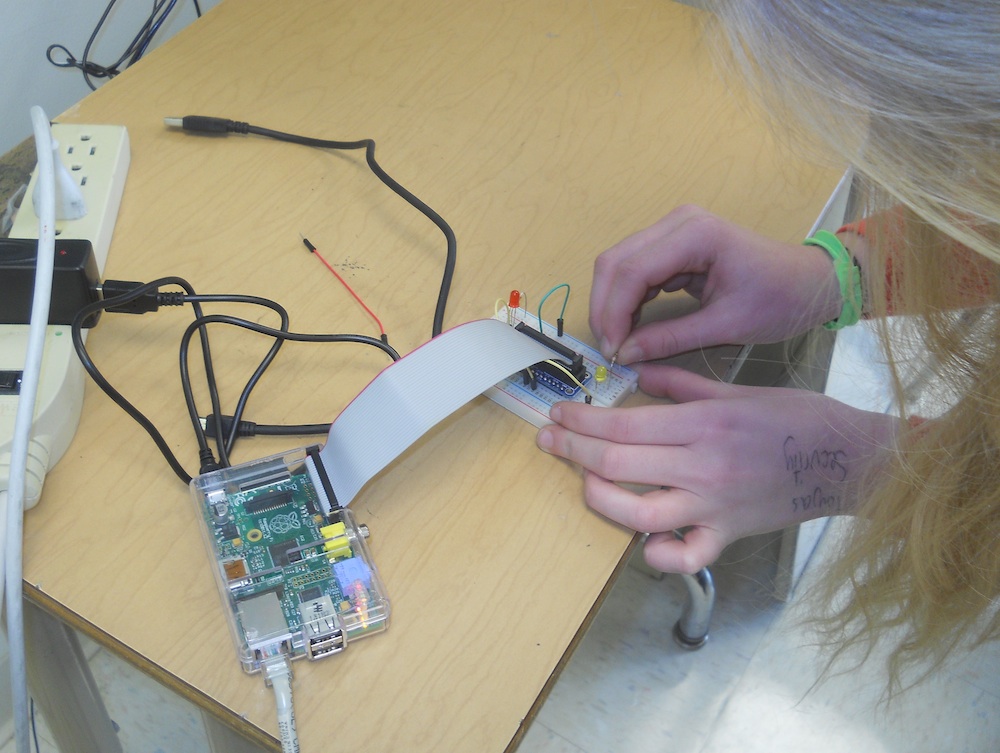
In order to get the Pi to operate the LED lights you have to control the pins that communicate in and out. Our starter kit came with a ribbon cable and breakout board that connects the pins from the Pi to a breadboard, which makes it easier to build circuits.
But first we have to be able to control to the Pi’s pins. I tried two different methods. The first was to use wiringPi, which is a set of command line tools, while the second was to use the Rpi.GPIO library for the Python programming language. We found it was much easier to use Python for its ease of programming.
Command line: wiringPi:
To get wiringPi, download it with ‘git‘, go to its directory, then build it (Gordon’s Projects has the instructions):
pi> git clone git://git.drogon.net/wiringPi
pi> cd wiringPi
pi> ./build
Now you can manipulate pin 0 (GPIO 17, which is labeled #17 on the breakout board) by: 1) setting to output mode; 2) turning it on, and; 3) turning it off:
pi> gpio mode 0 out
pi> gpio write 0 1
pi> gpio write 0 0
The following short script (red-light-flash.s) turns the light on and off ten times:
red-light-flash.s
#!/bin/bash
# a single blinking led light attached to gpio0
# based on
# https://projects.drogon.net/raspberry-pi/gpio-examples/tux-crossing/gpio-examples-1-a-single-led/

for i in `seq 1 10`
do
gpio write 0 1
sleep 0.5
gpio write 0 0
sleep 0.5
done
The script needs to be given execute permissions:
pi> chmod 777 red-light-flash.s
then run:
pi> ./red-light-flash.s
Python: Rpi.GPIO
As I mentioned above, it’s much easier to write programs in Python than to use shell scripts. So we’ll install the Python library, RPi.GPIO, to that allows us to communicate with the Pi. To get RPi.GPIO we first need the Python Development toolkit:
pi> sudo apt-get install python-dev
Then install Rpi.GPIO:
pi> sudo apt-get install python-rpi.gpio
To operate the GPIO-17 (turn it on and off every half second) we use the following program:
flash.py
#!/usr/bin/env python

from time import sleep
import RPi.GPIO as GPIO

cpr = 17  ## The GPIO Pin output number

GPIO.setmode(GPIO.BCM) ## Use board pin numbering

GPIO.setup(cpr, GPIO.OUT) ## Setup GPIO Pin 7 to OUT

for i in range(10):
	GPIO.output(cpr, True)
	sleep(0.5)
	GPIO.output(cpr, False)
	sleep(0.5)
GPIO.cleanup()
We run the program using the command:
pi> sudo python flash.py
Addendum: A Student’s Light and Sound Project
During our Creativity interim, one student chose to use the python program flash.py as a starting point to make a program to combine light and musical notes.


